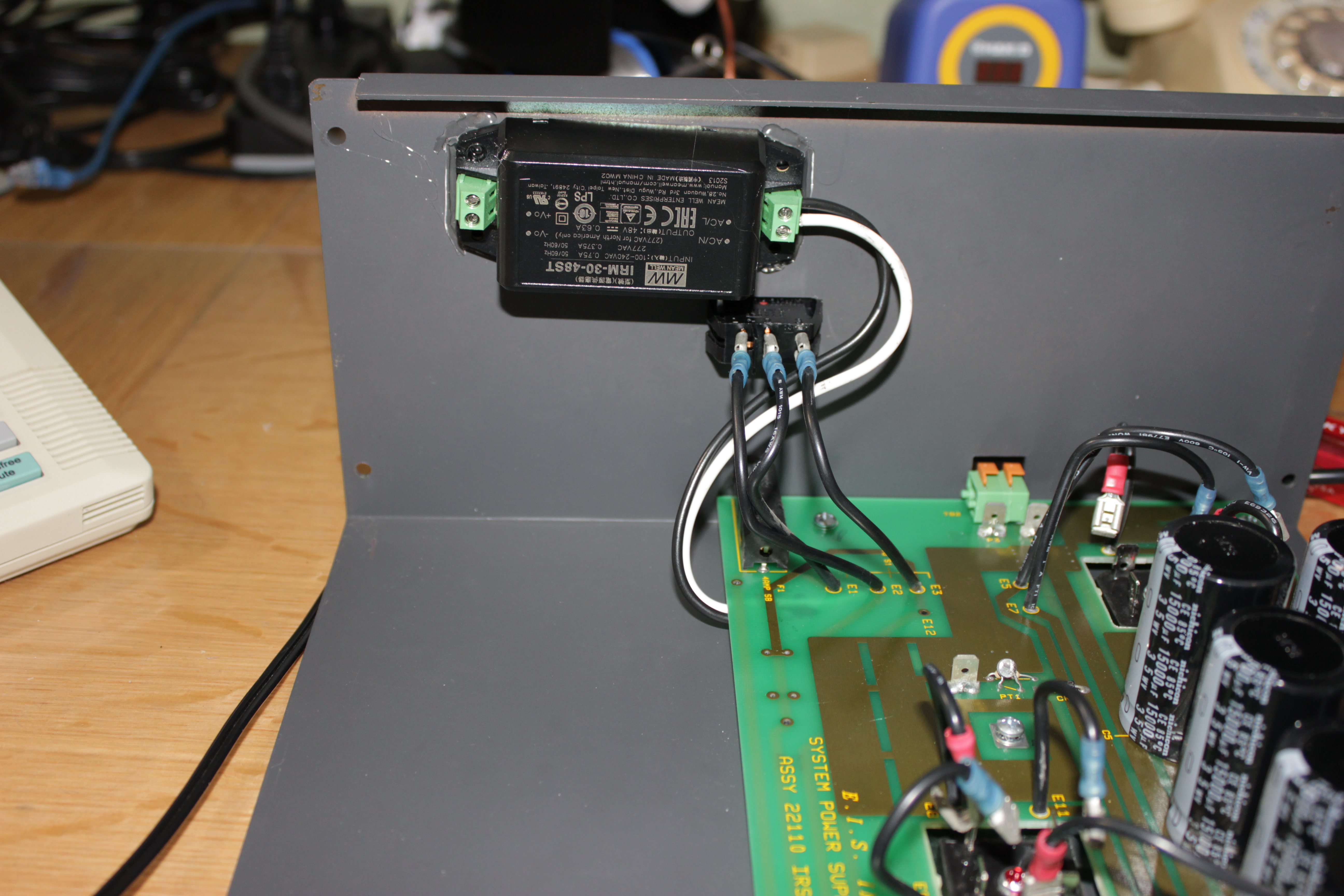
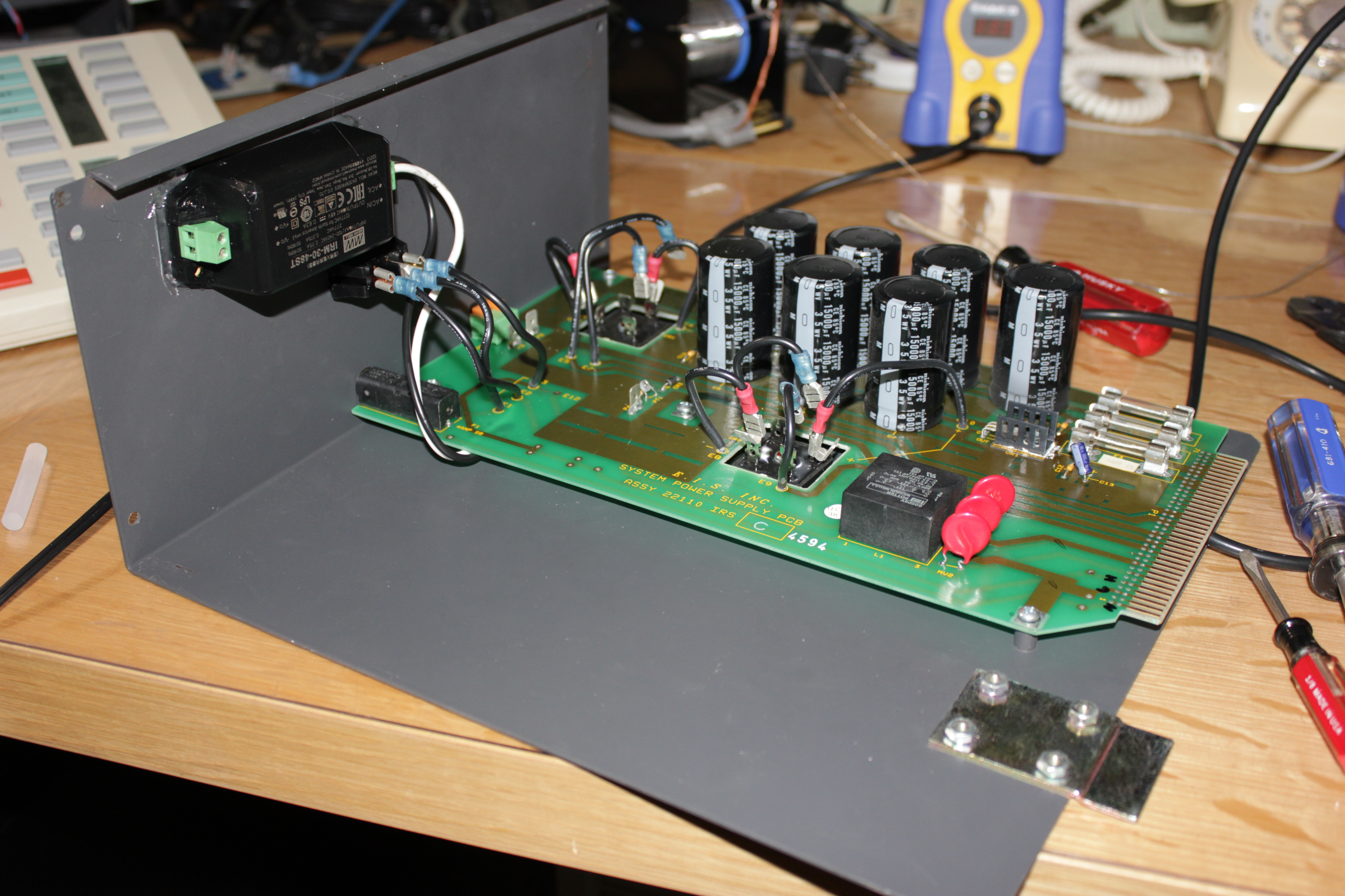
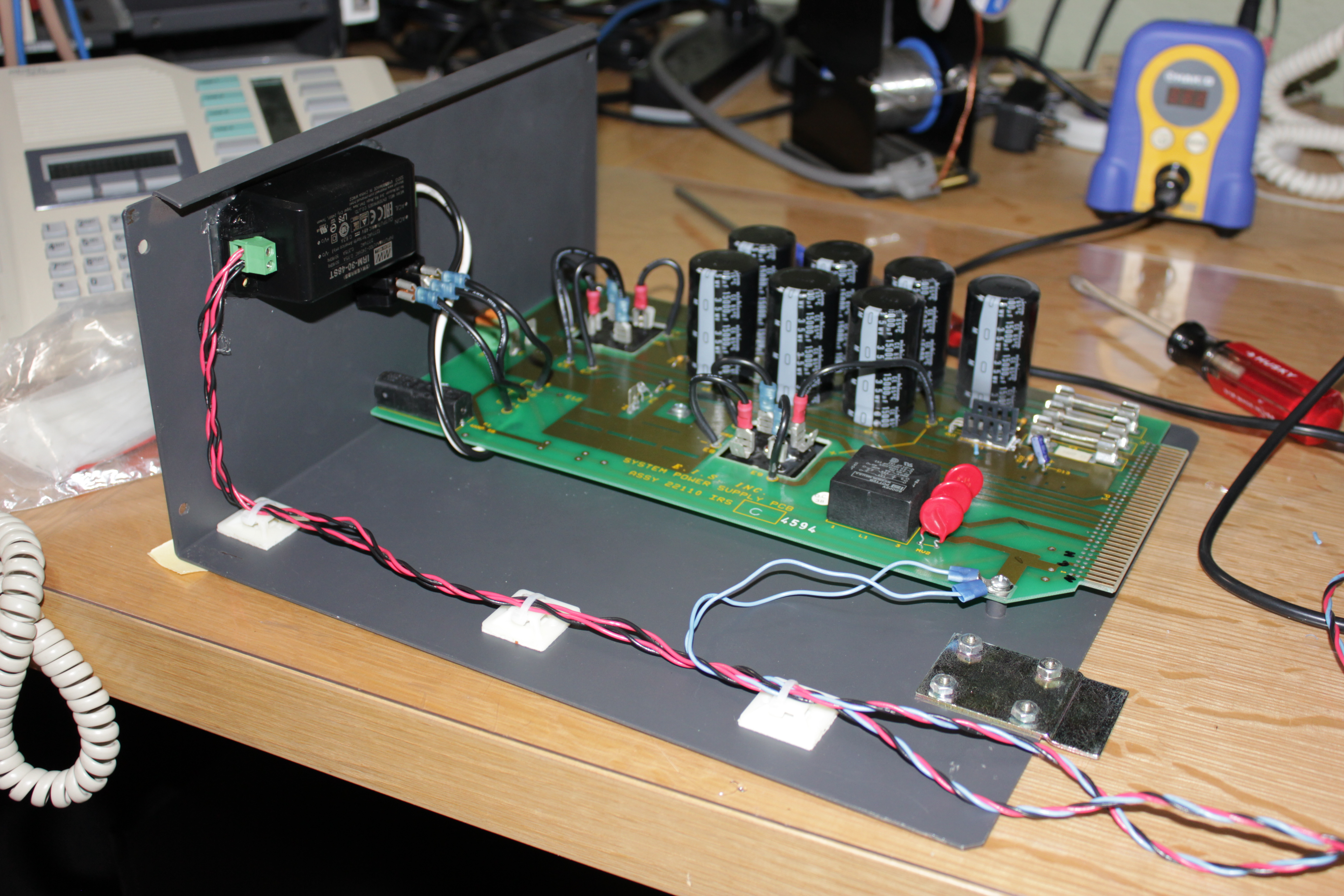
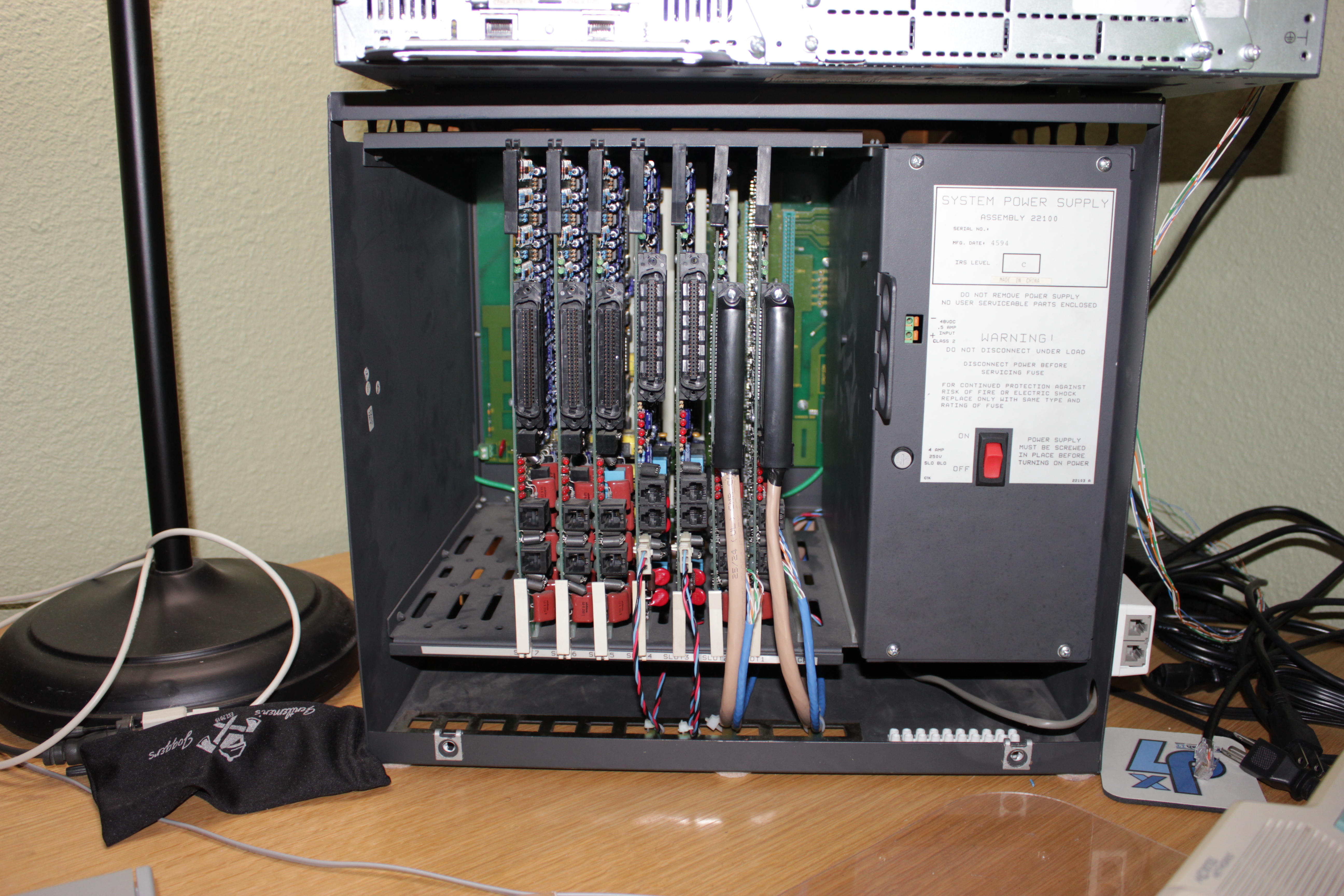
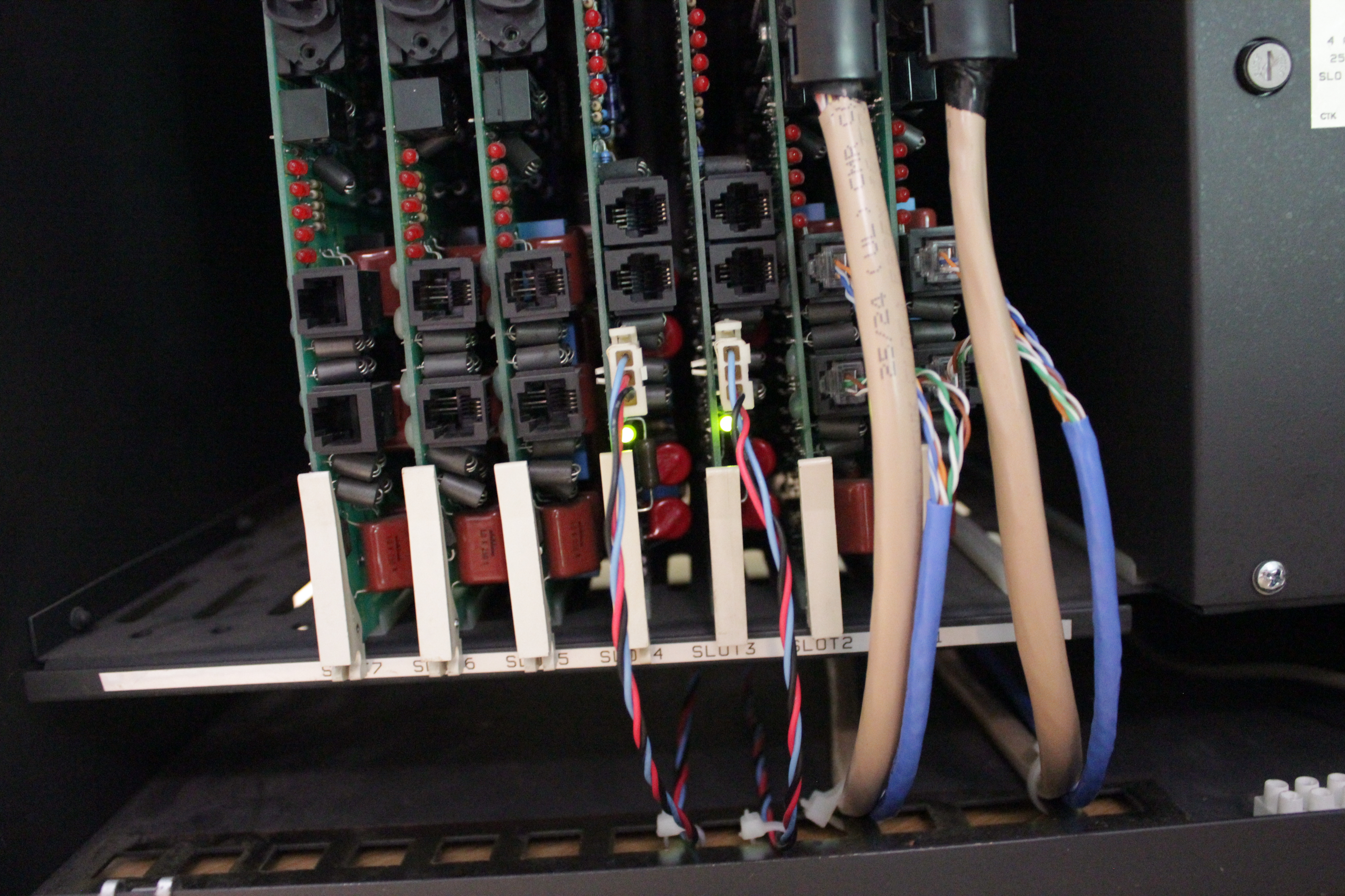
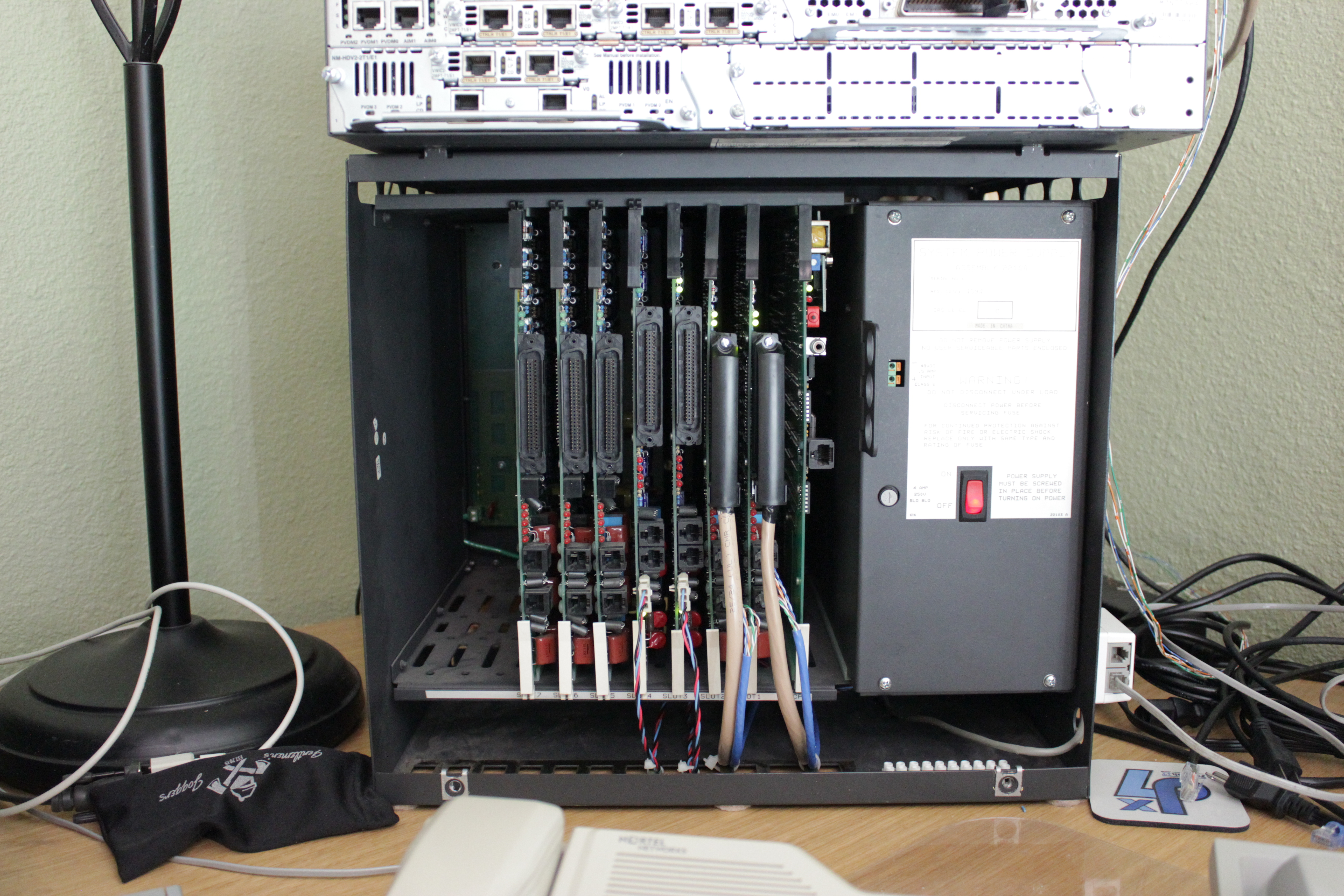
vodavi starplus digital psu modI have a Vodavi Starplus Digital 2856 PBX that I tinker with from time to time. Parts for the thing are more-or-less unobtainable, and when you do find them they're not cheap. However, I was able to snag a couple of 4x8 (4 trunk, 8 digital station) DID trunk cards for the thing. Because the receiving side of a DID trunks provides battery, the cards need a 48VDC source. For cards that need something other than 12VDC, it is BYO source. I could not find any documentation that detailed the specifications of the power source other than 48VDC. So I took a gamble and bought a Mean Well IRM-30-48ST PSU from Mouser. It's rated to output up to 30.2W (48VDC @ 0.63A) and will accept an input range of 85-264VAC. It's in a nice little form factor too and has screw terminals for both the input and output. The SPD 2856 utilizes a linear power supply constructed in a modular fasion. When you "remove" the power supply, you're actually removing a card with all of the components *except* the transformer. The transformer is mounted to the back of the chassis, and she's a big one. However, what this means is there is plenty of space in the cavity to stash other things. A perfect place for the Mean Well PSU! So, yes, this mod is a PSU inside a PSU, basically. I found a good spot to mount the Mean Well PSU, which is on the backside of the face of the bracket the PSU "card" mounts to. Because I did not want to modify the metal itself, I used a generous amount of hot glue to stick it in the position desired. It worked out better than I expected. It is firmly in place. I wanted to make sure that the Mean Well PSU was switched along with the rest of the system. I traced out the hot and neutral legs of the PSU and identified the switched side of the input. Interestingly, the neutral leg is the switched leg. Not the hot leg. Beacuse the switch is backlit by a neon lamp (which has developed that infamous flicker older backlit switches seem to develop), I also had access to the hot leg at the switch too. Once I identified the switched side, I tapped into it from the backside of the PSU card. I soldered down my hot and neutral wires (using the appropriate color coding) and used a bit of hot glue to insulate the solder joints from the bracket as well as to give the wire a little "strain relief". I wired everything up, put it all back together, and voala! We have an on-board 48VDC power source! I am quite happy with how things turned out. Links to photos of the endeavour are below. Picture 1 - Backside of the PSU card showing where I tapped into the high voltage side. |