lucent 16a announcement system
Posted March 14th, 2021
TL;DR - I snagged a Lucent 16A Announcement System. It needed a minor repair. I fixed it and it works. You may skip to the bottom if you're just here for the pictures.
I acquired a Lucent 16A Announcement Machine the other day. To say that I was excited to receive it is an understatement. Chances are pretty high that you have heard an intercept recording from one of these. Among other deployments, the 16A was a common announcement system paired with the WECo 5ESS switch. At any rate, it is my first piece of what I'd call "real" central office gear.
a tid bit about the 16a...
At a high level, the 16A provides the ability to record up to 24 different audio segments that can then be accessed over a DS1 trunk (in this case, CAS T1). The IC that handles storing the recordings is the ISD 2575P "chipcorder". The 16A uses up to 3 announcement "circuit packs" with each circuit pack handling 8 channels/recordings. The channels can be configured for continuous play (drum style announcements) or on-demand play (recording starts when the swich signals the channel) I'm still learning about the thing and will post more information as my knowledge expands.
back to your regularly scheduled rambing...
There were a few catches that came along with the 16A. The first catch, the power terminals were missing, so a repair was needed. The second catch was it did not come with any screws to secure the backplane to the chassis. The third catch was that the terminals to connect the unit to the network are wire wrap terminals. I don't own a wire wrap tool and have never done wire wrap terminations before. However, all of these "catches" I can totally handle.
First order of business was to get the thing power somehow. The backplane originally had screw terminals, but those were completely missing. The solder joints are through-hole, so it was simple enough to solder a length of cable directly to the backplane. Some Day (TM) I will source the appropriate screw terminals, but for now this is totally fine.
First dot five order of business was to supply the 16A with -48VDC. I, unfortunately, do not have a full blow -48VDC plant, so the few pieces of equiment I do have that are looking for it are on their own small PSUs. I happen to have a Mean Well IRM-30-48ST hanging around for another project. The question is, will this thing output enough current? I did a quick calculation based on the DC to DC converters located on the various cards and my math came out to 650mA. The Mean Well PSU is rated for 630mA. In skimming the manual, I found that it states maximum current draw is 800mA. Hmm. I *also* noticed "1A" screened to the side of the chassis. In theory, these ratings are all worst case, so I decided it would be OK to proceed ahead. It seems to work fine, but eventually I'll source a properly rated PSU and return the IRM-30-48ST back to it's original project. One thing you will notice when looking at the photos below is that I did not solder any wire to the ground terminal. I discovered that the ground terminal is simply a part of the backplane's ground as a whole. Once the 16A has a permanent home in my rack, I'm going to use an oval connector and provide ground via the chassis screw directly below where the ground terminal is located.
Seond order of business was to secure screws for the backplane. When I inherited this 16A, it was given to me completely disassembled...without any screws. After some himming and hawing as well as asking around, I decided it wouldn't hurt to lug the thing over to my local hardware store and see if I can find screws that'll work. Fortunately, I did! 4-40 machine screws were exactly what it needed (which was lucky as that was the smallest screw the local store carried). Picked up the necessary lengths and quantities, checked out, and made my way home to assemble.
Before assembling though, there was this 3rd catch of deciding how I wanted to terminate the DS1 connection. This is how the 16A interfaces with the network (AMI line coding, SF framing). Since I don't have a lick of wire wrap in my "home lab" (yet), I figured it would not be too blasphemous to tack on some wires to the back side of the DS1 terminals. I can easily undo it if/when the time comes. So, with that, I tacked on to the backside of the wire wrap terminals and snaked the wiring around through one of the cutouts in the backplane for the remote access line that can optionally be connected to each announcement circuit pack. I then terminated the wires to a 8P8C keystone jack following the RJ48 standard. I hot glued the keystone jack to an empty space on the backplane. I think this bit turned out pretty decent.
Once everything was all together, I powered the thing on. IT LIVES. I configured a T1 interface on one of the Cisco ISR2851's I have in my "home lab" appropriately. AMI line coding, SF framing, internal clock source (which means the Cisco provides clocking to the 16A), and the DS0's as FXO interfaces using E&M immediate start signalling. I created a test dial-peer to point a test extension to one of the channels, and...IT WORKS!
I need to complete another project before I can put the 16A in my rack. Once it has a permanent home, I'll post how you can dial in to hear announcements from the 16A. I plan to use it exactly how it was intended...to host the various intercepts I have set up for my voice network.
Ok, now the pictures (click thumbnail to enlarge):
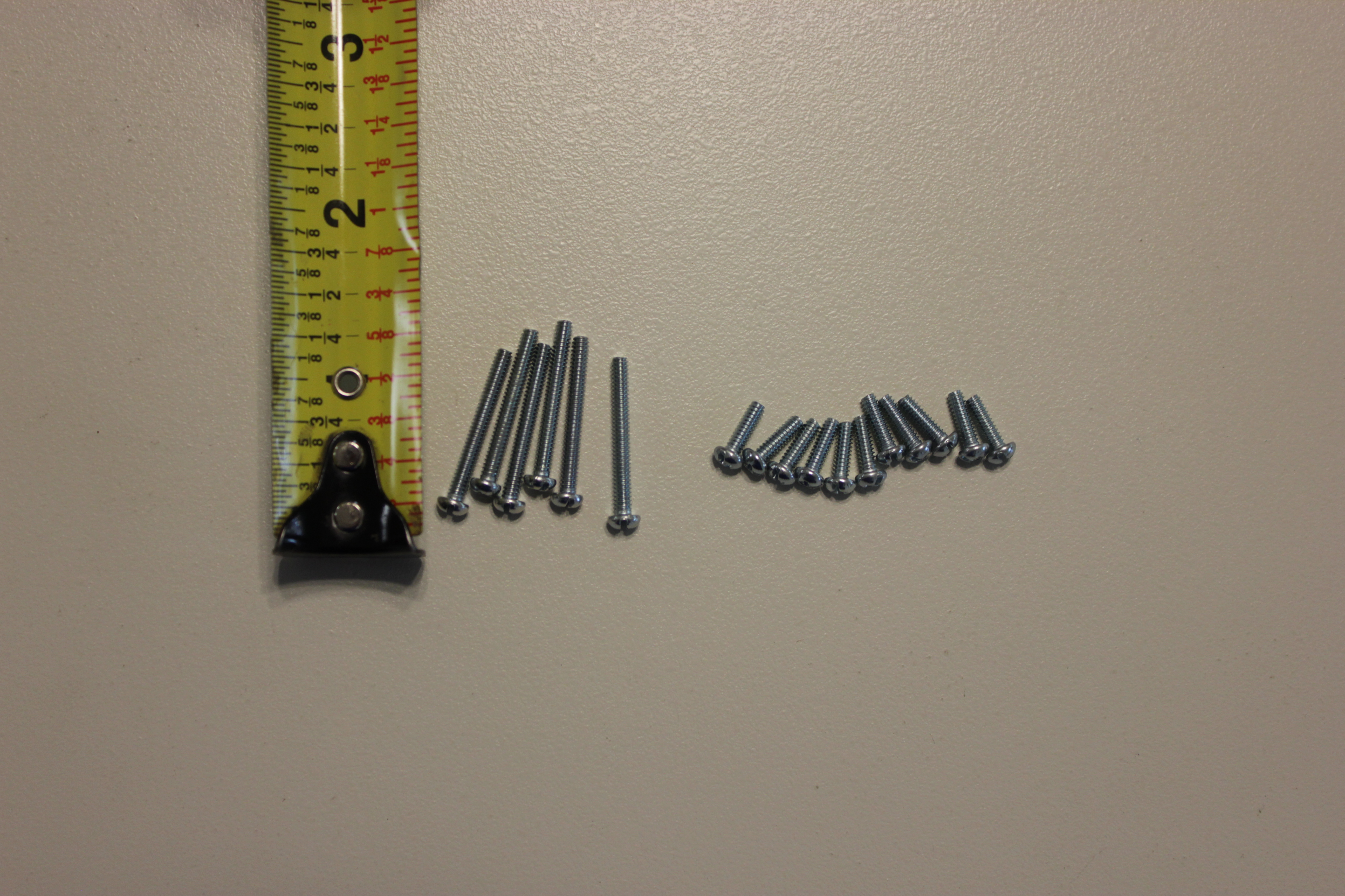 |
The screws I snagged from the local hardware store. 4-40 machine screws. The 11 short screws are for the backplain to chassis mount points. The 6 longer screws are for the backplane to announcement circuit pack via the amphenol connector. |
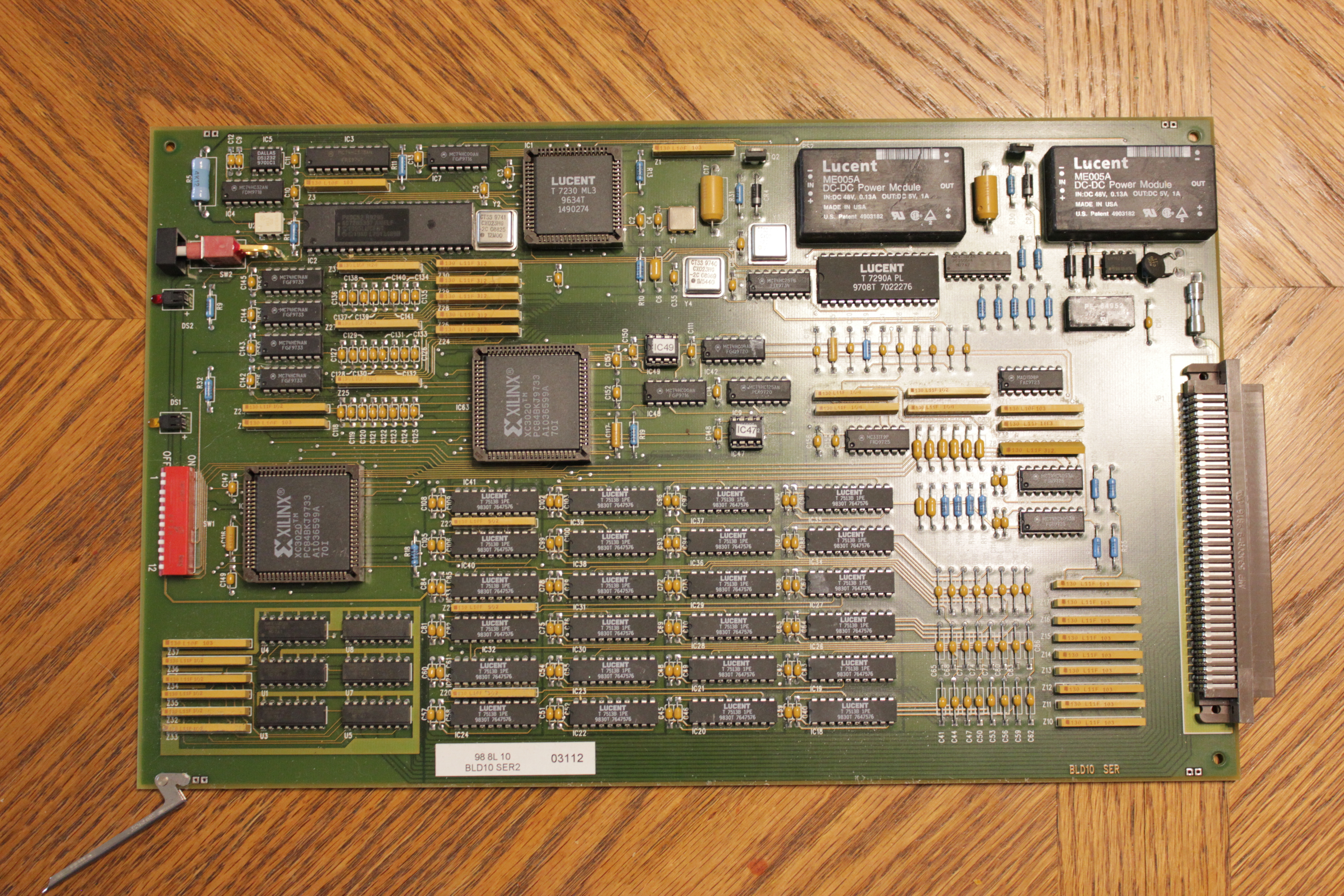 |
The digital interface circuit pack. This is how the 16A talks to the switch. |
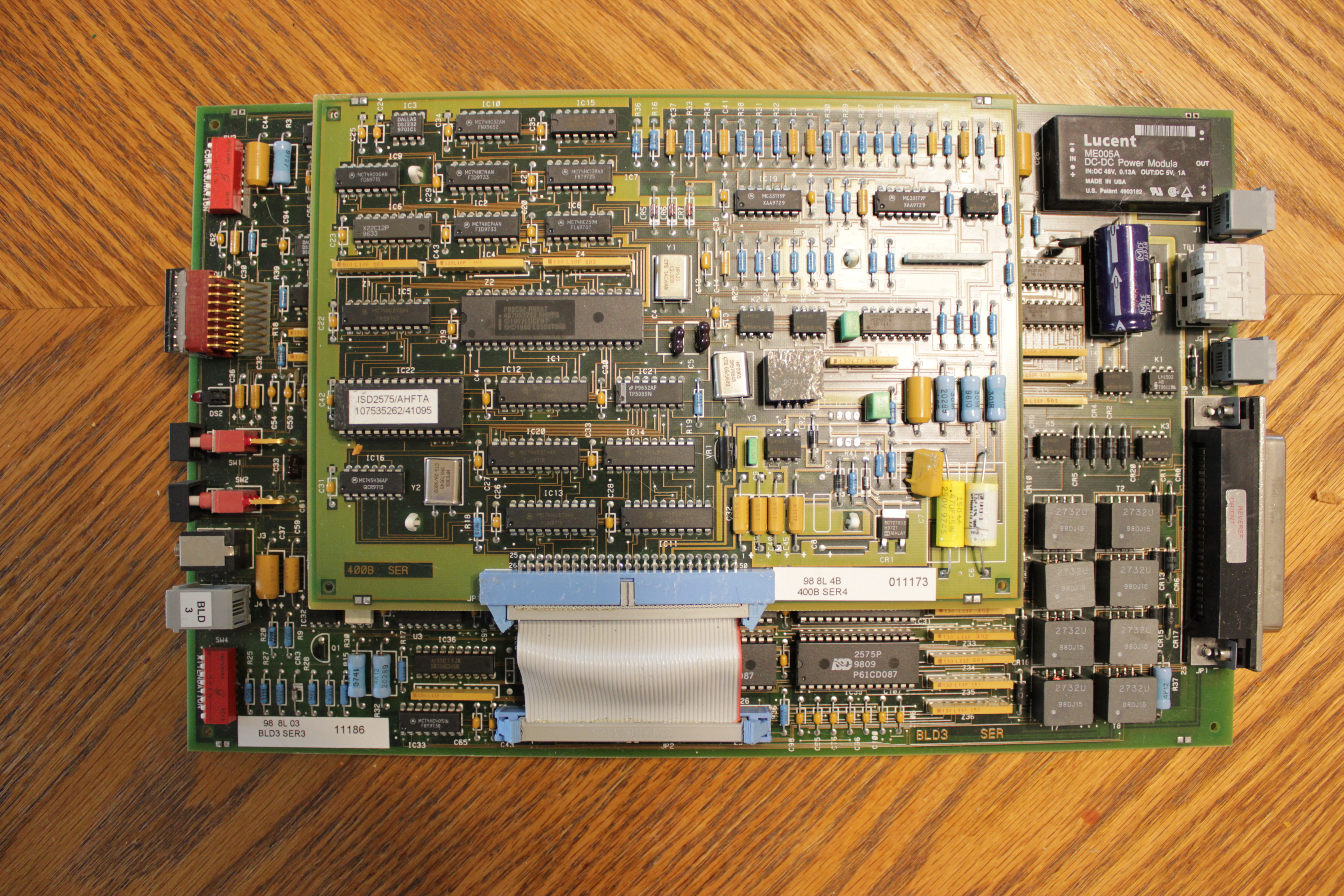 |
Top of an announcement circuit pack with the optional 400B Remote Record Module |
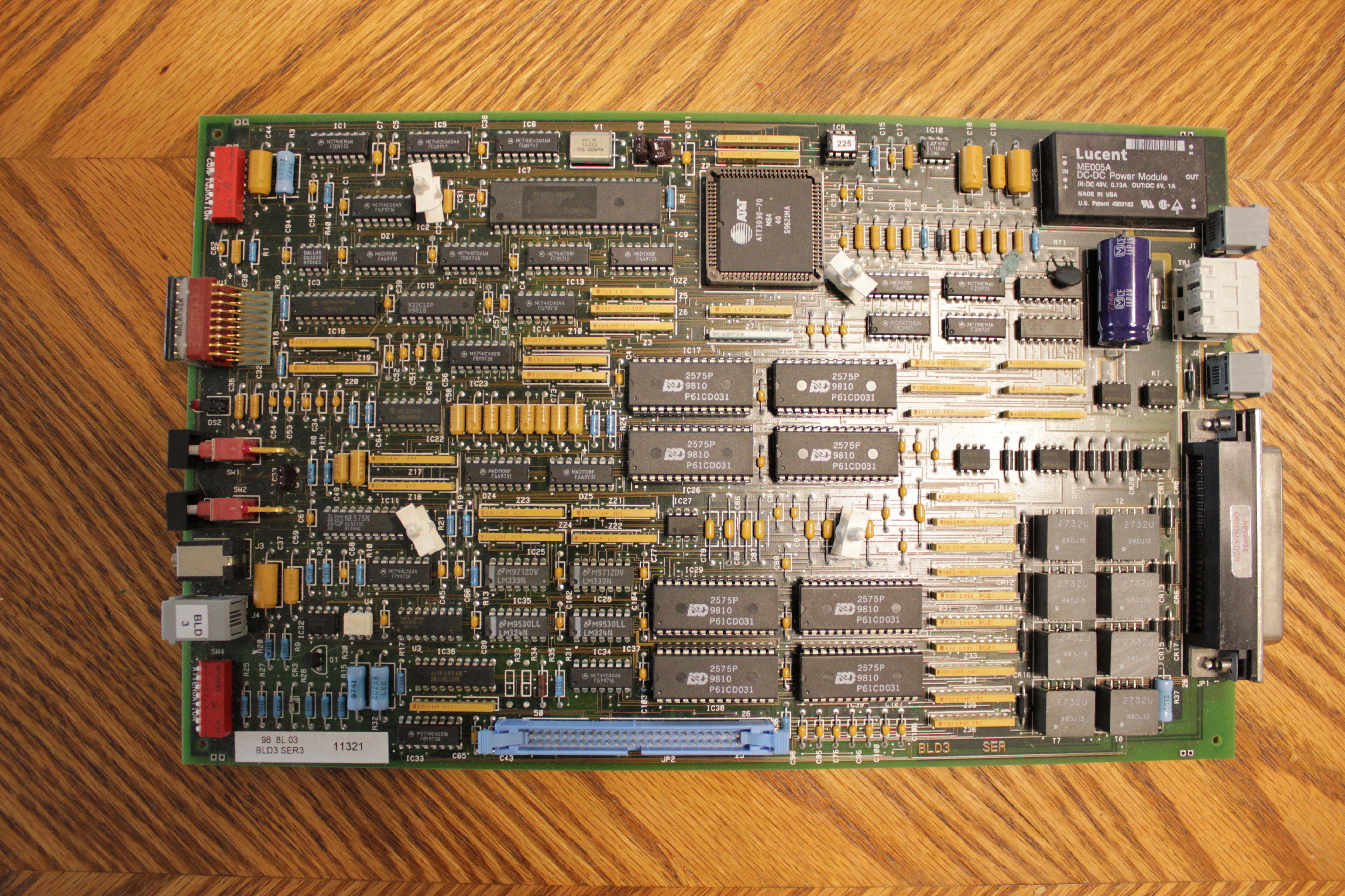 |
Top of an announcement circuit pack without the optional 400B Remote Record Module. You can see all 8 of the ISD 257P "chipcorder" ICs. |
 |
The back edge of an announcement circuit pack. Starting on the left you have the amphenol connector that interfaces with the backplane. Next to it is a modular jack for a loop start trunk for remote access (if equipped with a 400B daughter card). The screw terminals and additional modular jack I am not sure of their use. They are inacessible when the card is installed. My best guess is they're used when the pack is installed in a different chassis. |
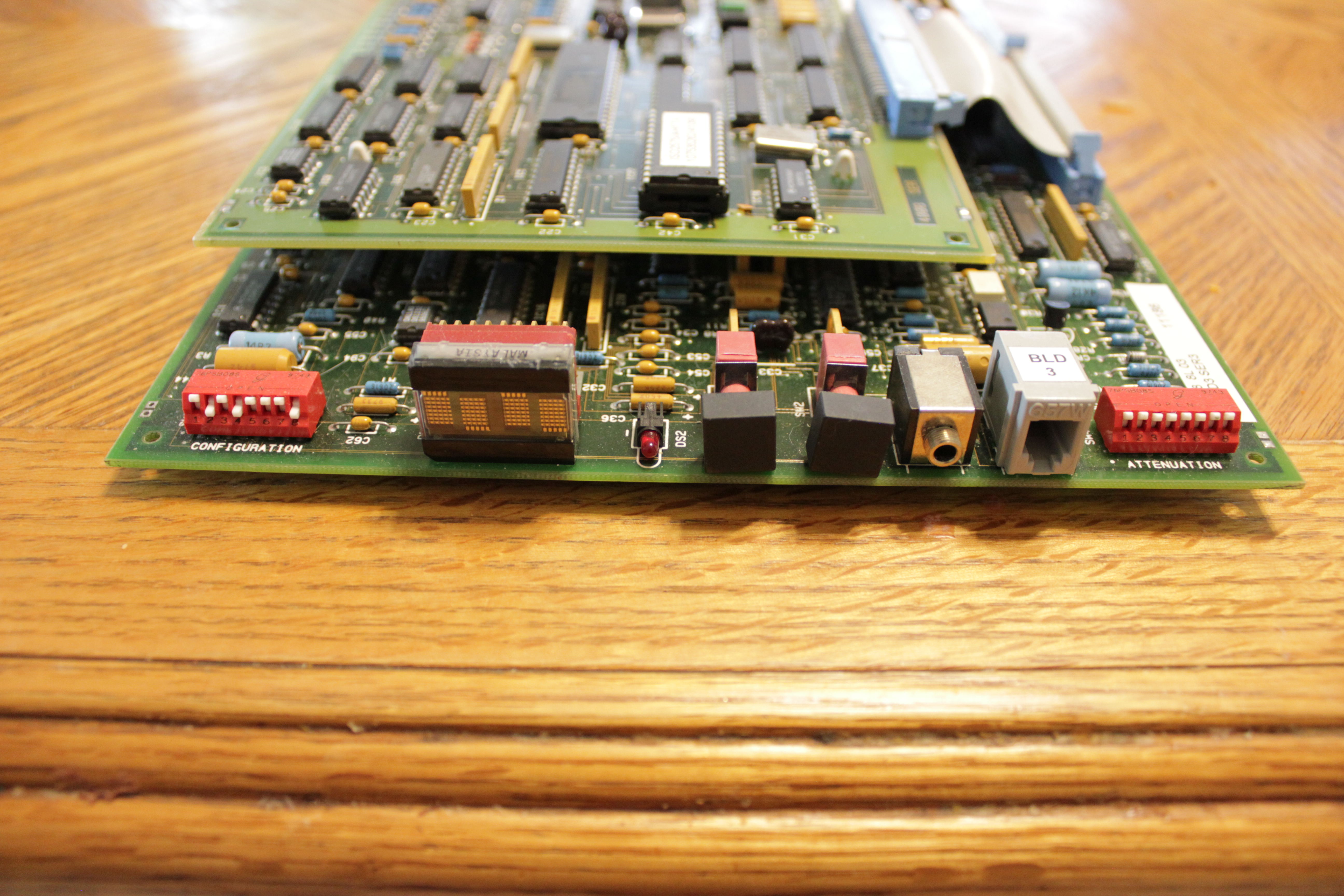 |
The front edge of an announcement circuit pack. Starting on the left you have DIP switches to control various card parameters, 4 segment LED display, menu button, select button, tape input, telephone handset connector for doing local recording/monitoring, DIP switches to control announcement attenuation. |
 |
The backplane. |
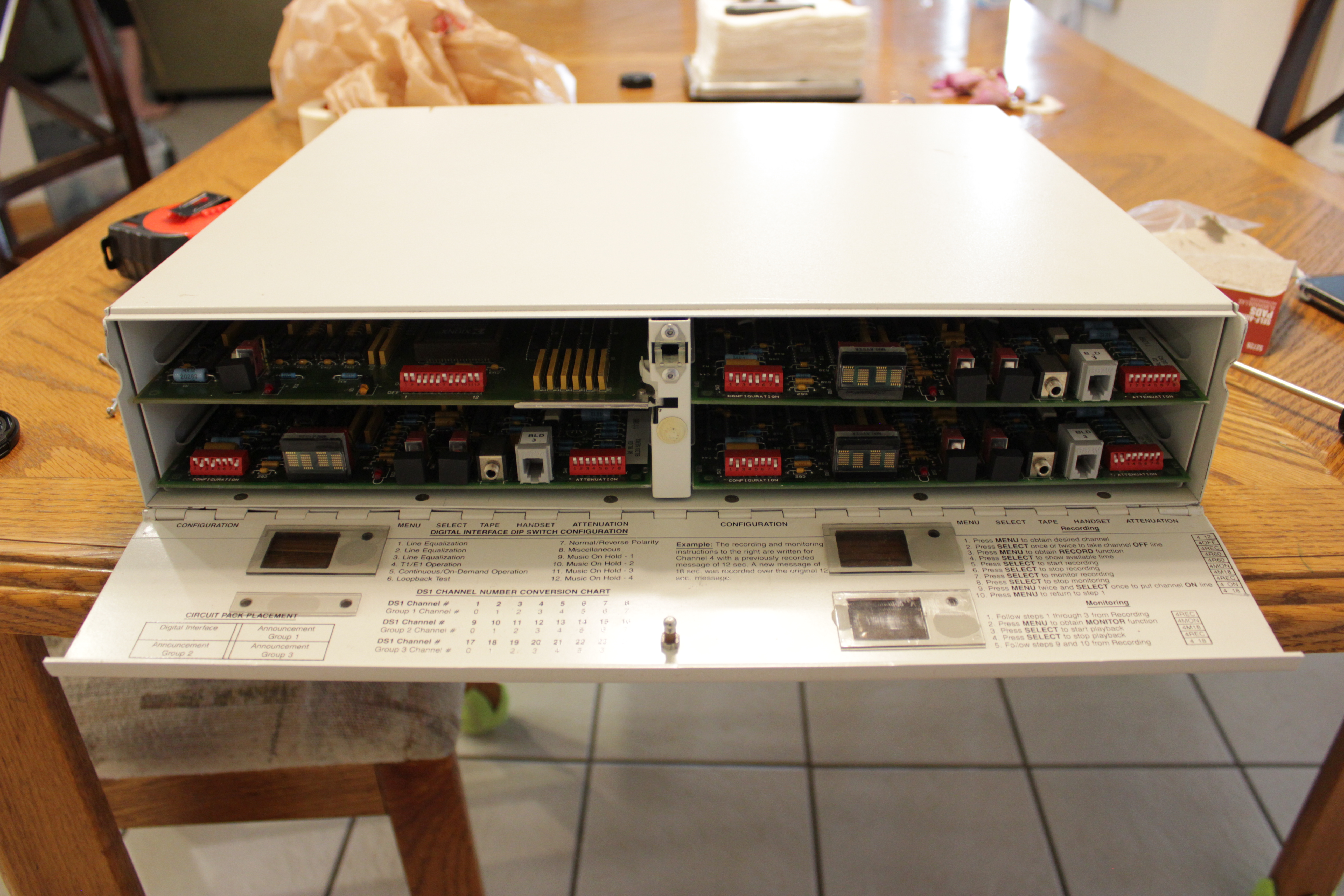 |
The front of the 16A with the face open. You can see the digital interface card in the upper left bay, then the 3 announcement circuit packs in the lower left bay and the two right bays. |
 |
This is how I tapped into the DS1 terminals. Not the prettiest, but it is functional. Definitely not to Bell System specifications, heh. |
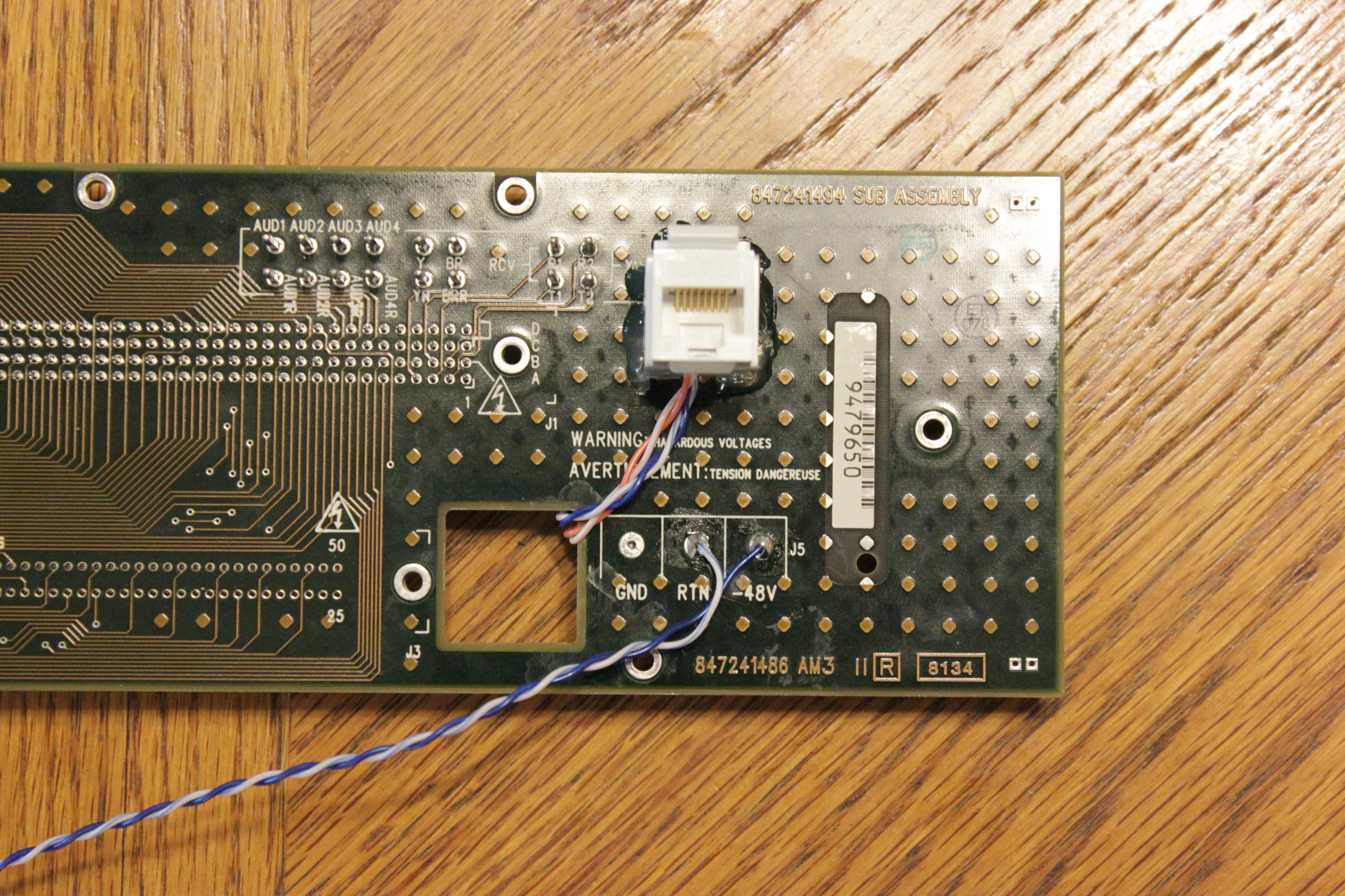 |
And how I terminated the wiring for the DS1 connection. The hot glue hold the keystone jack very well. Again, definitely not Bell System compliant. |
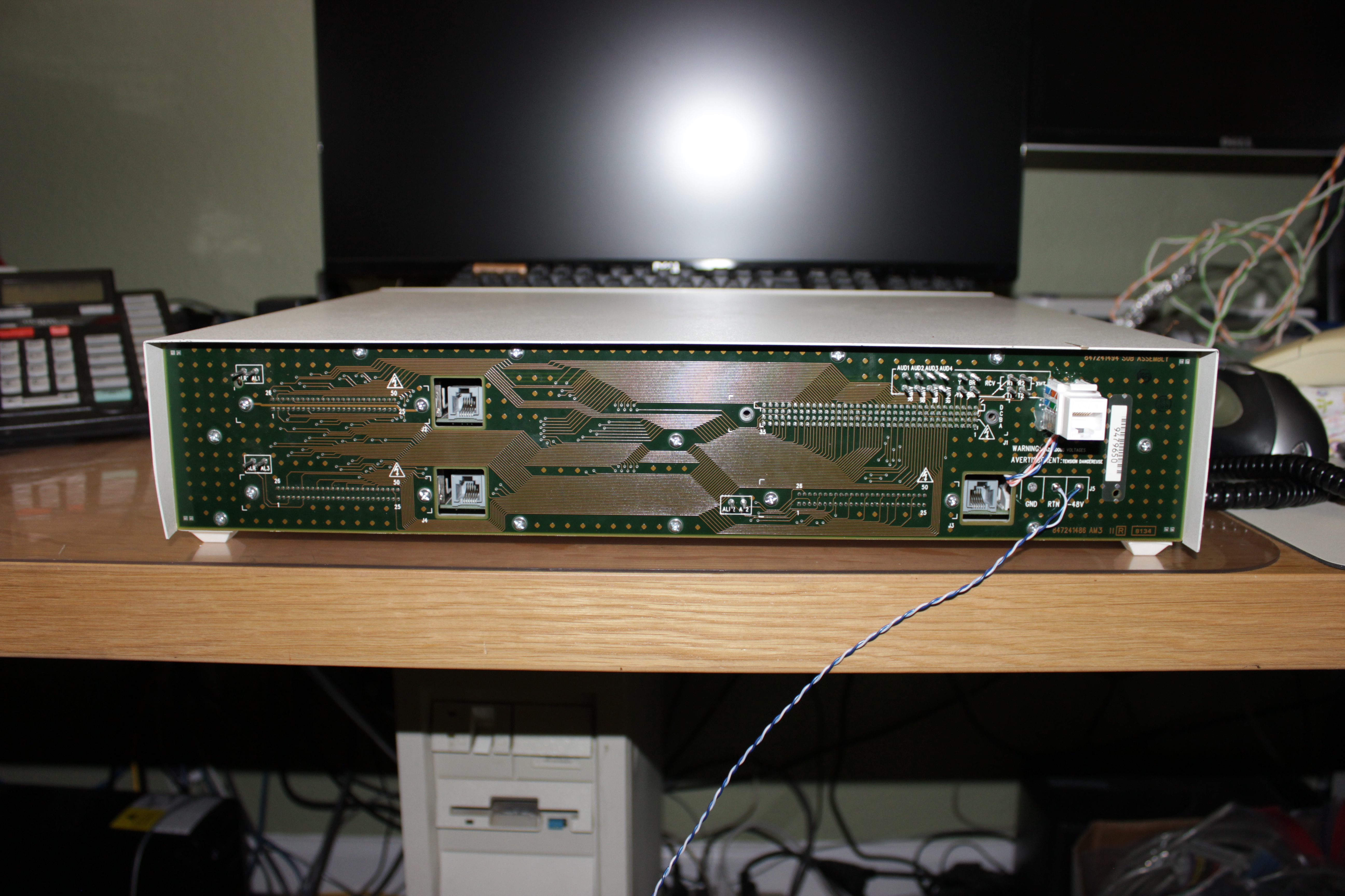 |
View of the backplane after the 16A was fully assembled. |
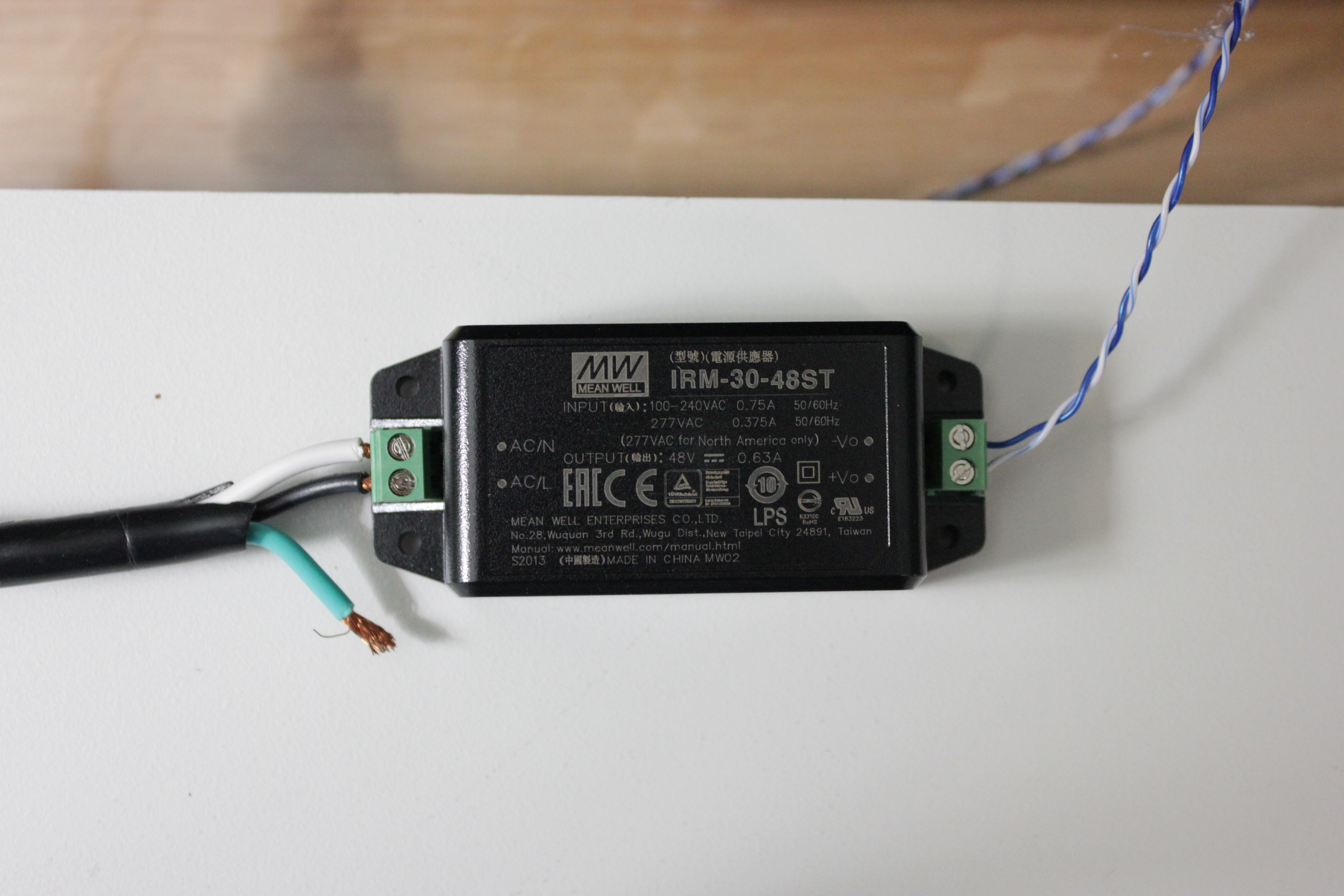 |
The Mean Well PSU I rigged up. |
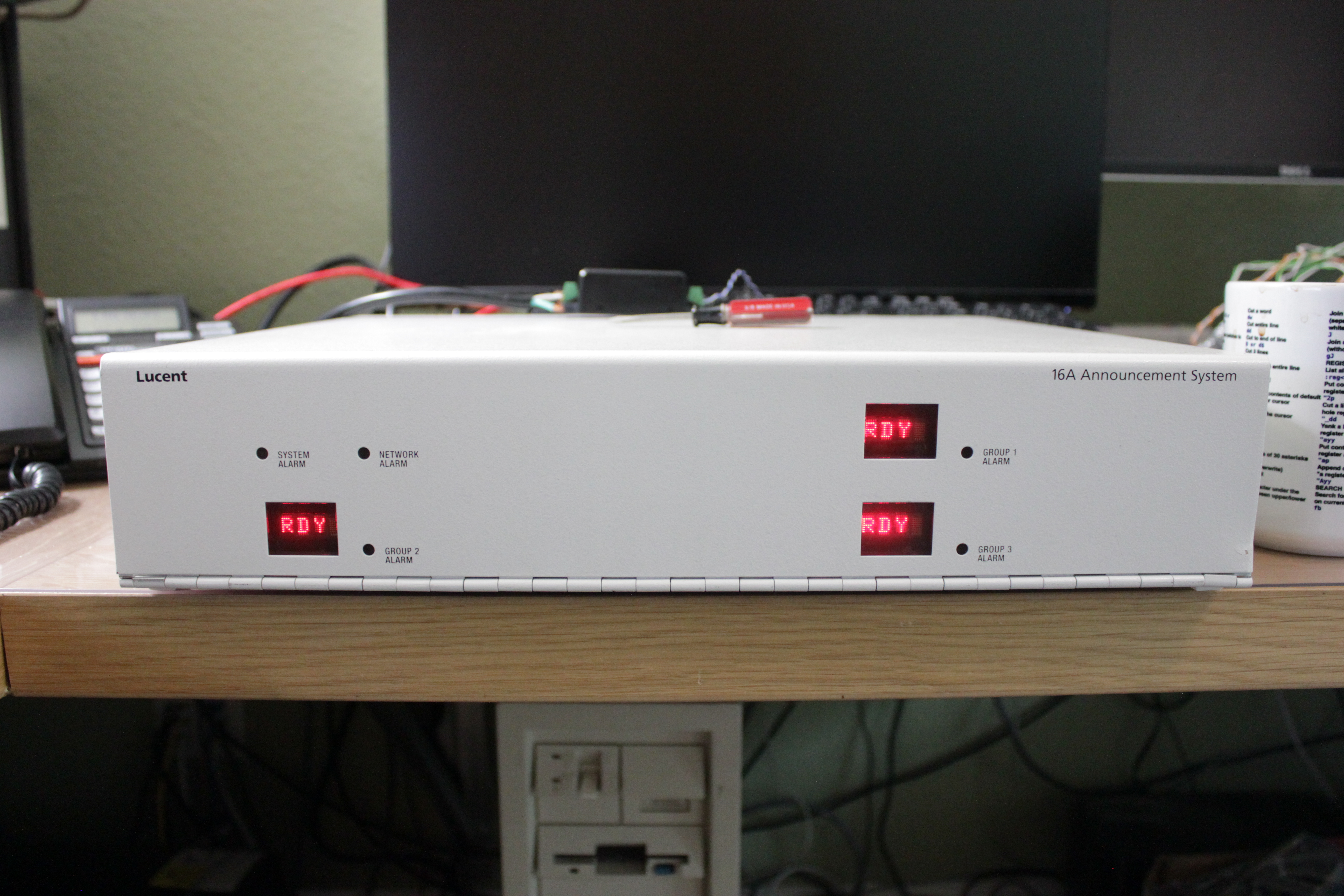 |
The 16A lives! I love the LED displays. |
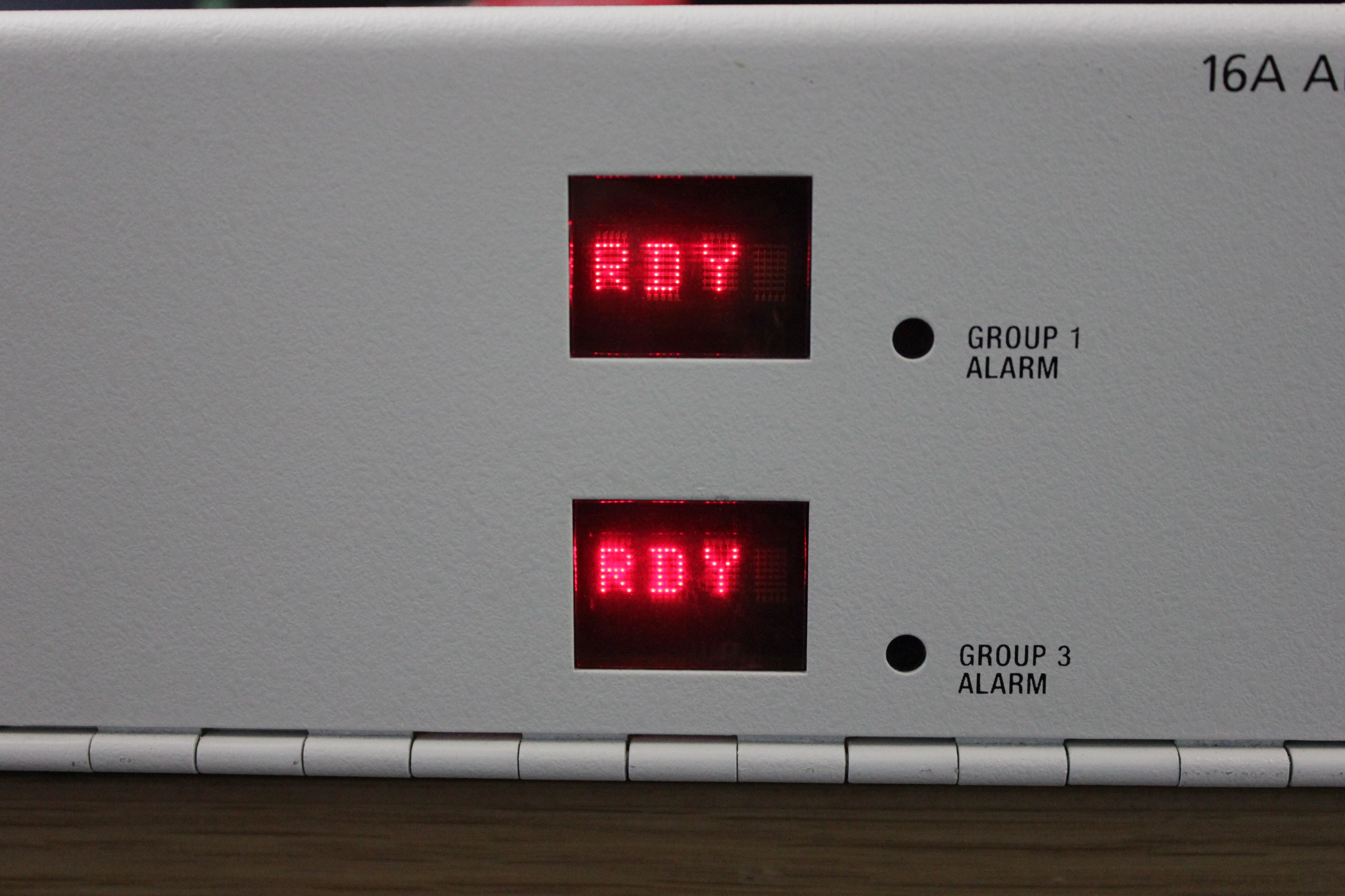 |
Up close shot at the LED displays. |
You can find the 16A Announcement System manual here.